This section describes the procedure for establishing basic empty weight and moment of the aircraft. Information on loading procedures is also provided.
Date: __________
Datum: Propeller support flange without spacer Equipment list, date: __________
MAC: 1400 mm
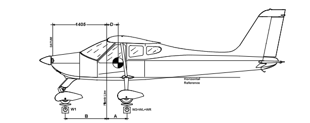
| Nose wheel weight | W1 = |
| LH wheel weight | WL = |
| RH wheel weight | WR = |
| W2 = WL + WR | = |
| Plumb line distance LH wheel | AL = |
| Plumb line distance RH wheel | AR = |
| Average distance (AL+ AR)/2 | A = |
| Plumb line distance from nose wheel | B = |
Empty weight(1): We = W1 + W2 = __________ kg
D = (W2 · A - W1 · B) / We = __________ m
D% = (D / 1.4) · 100 = __________%
Empty weight moment: M = [(D + 1.405) · We] = __________ Kg·m
| WT = 550 kg | WT = 600 kg | Signature: | |
|---|---|---|---|
| Maximum takeoff weight | WT = 550 kg | WT = 600 kg | |
| Empty weight | We = | We = | |
| Max useful load WT - We | Wu = | Wu = |
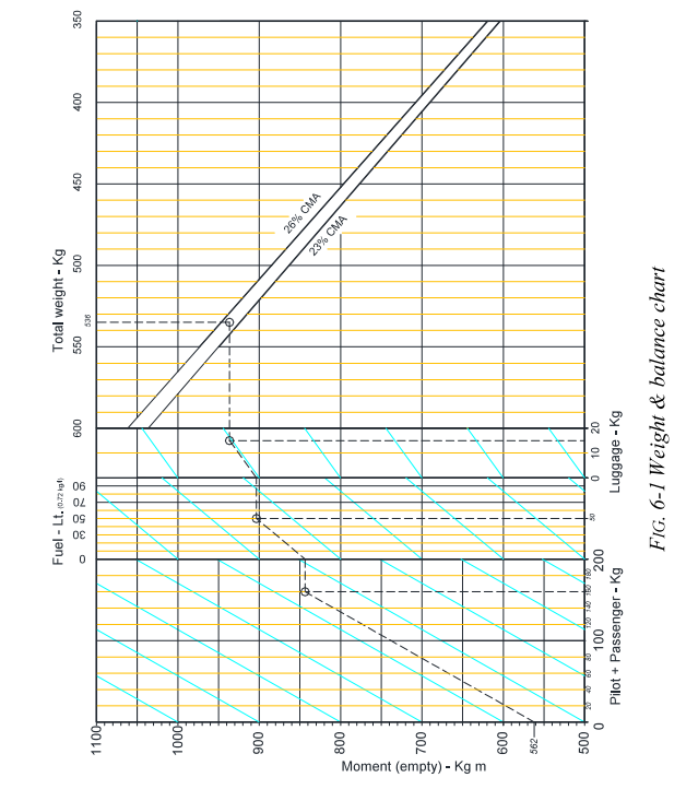
To determine the aircraft C.G. position and verify that the C.G. falls within the predetermined allowable range, it is necessary to use the graph on the following page. The graph shows the C.G. position as a function of the empty weight moment with respect to the datum as resulting from the weighing report.
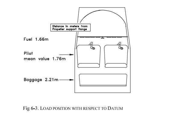
To use the graph it is necessary to know the value of the moment arm with respect to the datum. Once this value is found on the abscissa, draw a line parallel to the oblique lines until it intersects the ordinate relative to pilot and passenger weight. From this point, draw a horizontal line to the limit value of 180 kg and, from there, draw a line parallel to the oblique lines until it intersects the abscissa relative to the fuel loaded. Then draw a horizontal line through this point to the limit value of 70 liters and a new line parallel to the oblique lines until it intersects the abscissa relative to the baggage loaded behind the seats.
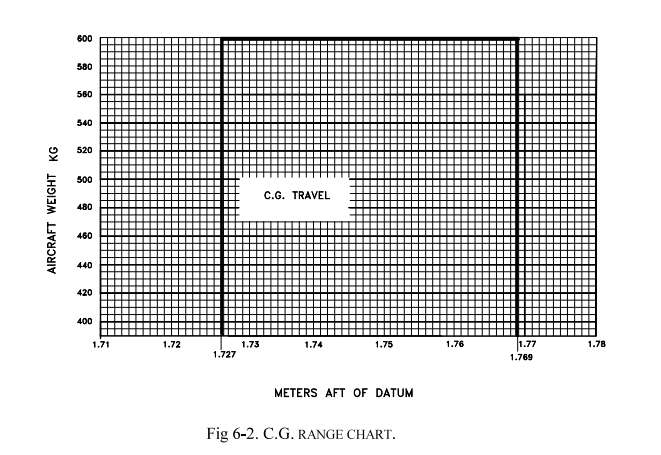
Draw another horizontal line and it is thus possible to verify that the intersection of this segment with the vertical abscissa relative to the total takeoff weight of the aircraft falls within the shaded area representing the allowable C.G. range as a function of total weight.
Pages 6-6 and 6-7 show the C.G. range graphs as a function of aircraft weight, the distances in meters of pilots and baggage from the datum (propeller support flange).
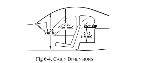
The baggage compartment is designed for a maximum load of 20 kg. Baggage dimensions must avoid excessive loading of the service shelf (maximum pressure 12.5 kg/dm2). Maximum baggage dimensions: 80 x 45 x 32 cm. Baggage must be secured with a tie-down net to prevent any movement during maneuvers.
Below is a complete list of all equipment supplied by TECNAM for the P92-JS. The list is composed of the following groups:
The following information describes each item in the list:
| Ref. | Description and P/N | Inst. | Weight kg | Datum m |
|---|---|---|---|---|
| A1 | Engine Rotax 912S2 - p/n 309.120.133 | * | 59.0 | 0.32 |
| A2 | Propeller HOFFMANN p/n HO17GHM A 174 177C | * | 4.50 | -0.08 |
| A3 | Exhaust and manifolds - p/n SSB-978-480-CC | * | 4.50 | 0.55 |
| A4 | Heat exchanger - p/n 92-11-830 | * | 2.00 | 0.55 |
| A5 | Oil tank (full) - p/n 956.137 or 656.865 | * | 4.00 | 0.61 |
| A6 | Oil radiator - p/n 886 025 or 886.033 | * | 0.40 | 0.07 |
| A7 | Coolant radiator - p/n 995.697 or 997.083 | * | 0.90 | 0.33 |
| A8 | Air filter K&N - p/n 33-2544 | * | 0.40 | 0.60 |
| A9 | Vacuum instruments system - RA215CC Rapco | 3.00 | 0.25 | |
| A10 | Vacuum valve RA2H3-12 | 0.100 | 0.71 | |
| A11 | Fuel pump p/n 21-11-342-000 | * | 0.200 | 0.71 |
| A12 | Fuel tank 45 Lt. P/N 21-1-340-001/2 | * | // | // |
| Ref. | Description and P/N | Inst. | Weight kg | Datum m |
|---|---|---|---|---|
| B1 | Main gear leaf springs - p/n 92-8-300-1 | * | 5.700 | 1.930 |
| B2 | Main wheel rims - CLEVELAND 40-78B or 199-102 | * | 2.050 | 1.930 |
| B3 | Main tires - AIR TRAC 5.00-5 | * | 2.580 | 1.930 |
| B4 | Disc brakes - Cleveland 30-9 or 160-17 | * | 0.800 | 1.930 |
| B5 | Nose wheel rim p/n 92-8-880-1 or 92-8-700-000 | * | 1.300 | 0.310 |
| B6 | Nose tire - 4.00-6 | N | 1.200 | 0.460 |
| B7 | Nose tire - AIR TRACK 5.00-5 | 1.500 | 0.460 | |
| B8 | Nose wheel fairing p/n 92-8-410-1/2 | N | 1.500 | 0.460 |
| B9 | Nose wheel fairing p/n 27-8-420-1 | 1.500 | 0.460 | |
| B10 | Main wheel fairing p/n 92-8-420-1/2 | x | 1.500 | 1.930 |
| B11 | Nose shock absorber p/n 92-8-200-000 | * | 1.450 | 0.465 |
| Ref. | Description and P/N | Inst. | Weight kg | Datum m |
|---|---|---|---|---|
| C1 | Battery FIAMM 6H4P 12V 18Ah | 6.00 | 4.24 | |
| C2 | Regulator, rectifier - p/n 945.345 | * | 0.20 | 0.82 |
| C3 | Battery relay - p/n 111-226-5 | * | 0.30 | 4.19 |
| C4 | Flap actuator - SIR Mod. AO-01/M | * | 2.20 | 2.57 |
| C5 | Flap actuator switch - FEME MS35059-34 | * | 0.08 | 1.20 |
| C6 | Trim actuator control Ray Allen C. T2-10A | * | 0.40 | 5.75 |
| C7 | Overvoltage sensor OS75-14 | 0.30 | 0.80 | |
| C8 | Overvoltage sensor B00289-2 | * | 0.30 | 0.80 |
| C9 | Strobe light - p/n 2005 | N | 0.15 | 5.52 |
| C10 | Navigation lights - AS W1285 | N | 0.15 | 2.30 |
| C11 | Nav-Strobe light - AVE-WPTSG-54G | 0.25 | 2.30 | |
| C12 | Stall warning AS 164R or TECNAM 21-9-420-000 | * | 0.10 | 1.95 |
| C13 | Landing light - AS GE 4509 | 0.50 | 1.50 | |
| C14 | Landing light - Pled1L | 0.60 | 1.50 | |
| C15 | BATTERY SPARK 500 | 4.9 | 4.24 |
| Ref. | Description and P/N | Inst. | Weight kg | Datum m |
|---|---|---|---|---|
| D1 | Altimeter - MIKROTECHINA p/n 1128.12B6 | 0.39 | 1.20 | |
| D2 | Altimeter - United Instruments p/n 5934PM-3 | 0.39 | 1.20 | |
| D3 | Airspeed indicator - MIKROTECHINA 116.B0B2 | * | 0.30 | 1.20 |
| D4 | Compass - Airpath C2400 L4P | * | 0.29 | 1.20 |
| D5 | Clock - DAVTRON mod. M 800 | * | 0.15 | 1.20 |
| D6 | Variometer - MIKROTECHINA UL 30-42.2 | 0.35 | 1.20 | |
| D7 | Variometer - Wultrad Inc. p/n BC-2A | 0.35 | 1.20 | |
| D8 | Turn and slip indicator - FALCON GAUGER TC02F-3-2 | 0.56 | 1.20 | |
| D9 | Turn and slip indicator - Mid. Continent p/n 1394T100-TZ | 0.56 | 1.20 | |
| D10 | Attitude indicator - FALCON G. GH02V-3 | 1.10 | 1.20 | |
| D11 | Attitude indicator - RCA ALLEN INSTR. RCA 22-7 | 1.10 | 1.20 | |
| D12 | Directional gyro - RCA ALLEN INSTR. RCA 11A-8 | 1.10 | 1.20 | |
| D13 | Directional gyro - FALCON G. DG02V-3 | 1.10 | 1.20 | |
| D14 | OAT indicator - 397035001G VDO | * | 0.05 | 1.20 |
| D15 | CHT indicator - 641-011-7047/-7048 VDO | N | 0.10 | 1.20 |
| D16 | CHT indicator - Ind. SOR 53 or SOR 59 | * | 0.10 | 1.20 |
| D17 | Oil temp indicator - VDO 644-001-7030 | N | 0.10 | 1.20 |
| D18 | Oil temp indicator - SOR 54 | * | 0.10 | 1.20 |
| D19 | Vacuum instruments - UMA Inc. 3-200-12 | * | 0.10 | 1.20 |
| D20 | Prop RPM indicator - D1-112-5040 Aircraft Mitchell | N | 1.10 | 1.20 |
| D21 | Prop RPM indicator - Sorlini (SOR52) | * | 1.10 | 1.20 |
| D22 | Fuel level indicator - Road XID4.0008.00 | * | 0.56 | 1.20 |
| D23 | Oil pressure indicator - Sorlini (SOR50, SOR50V) | 0.10 | 1.20 |
| Ref. | Description and P/N | Inst. | Weight kg | Datum m |
|---|---|---|---|---|
| E1 | Nav/Comm Trans. - Bendix/King KX155 | 2.24 | 1.20 | |
| E2 | Nav indicator - Bendix/King KI208 | 0.46 | 1.20 | |
| E3 | R/T VHF COMM Garmin SL40 | 1.20 | 1.20 | |
| E4 | Transponder - Bendix/King KT76A | 1.36 | 1.20 | |
| E5 | GPS/NAV receiver and COM r/t GNS 430W | 2.31 | 1.20 | |
| E6 | R/T VHF COMM IC-A200 ICOM | 1.20 | 1.20 | |
| E7 | ELT ARTEX ME 406 | 1.10 | 2.70 | |
| E8 | Transponder - Garmin GTX328 or GTX335 | 1.00 | 1.20 | |
| E9 | Audio panel - Garmin GMA 340 or 345 | 0.50 | 1.20 | |
| E10 | VOR/Loc indicator - Garmin GI106( ) | 0.64 | 1.20 | |
| E11 | Antenna KA 92 GPS | 0.27 | 1.07 | |
| E12 | Transponder antenna - Bendix/King KA60 | 0.35 | 1.50 | |
| E13 | GPS antenna - Garmin 1012 | 0.17 | 1.07 | |
| E14 | Microphone - Telex TRA 100 | 0.17 | 1.90 | |
| E15 | Antenna Garmin GA35 | 0.27 | 1.08 | |
| E16 | Comm antenna CI 291 or CI 121 | * | 0.34 | 3.30 |
| E17 | VOR/ILS antenna CI 138C or CI 158C | 0.26 | 5.60 | |
| E18 | ELT antenna | 0.21 | 2.70 | |
| E19 | Fire extinguisher Fire Fighting Enterprises Ltd BA51015-3 | 2.20 | 2.16 | |
| E20 | Fire extinguisher - HALON H3G 1301 or AMEREX A344 | 1.00 | 2.16 | |
| E21 | First aid kit | * | 0.28 | 2.60 |
| E22 | Altitude encoder - Amery King A30 | 0.56 | 1.00 | |
| E23 | ADF receiver - Bendix King KR87 | 1.38 | 1.20 | |
| E24 | ADF indicator - Bendix King KI227 | 0.39 | 1.20 | |
| E25 | ADF antenna - Bendix King KA44B | 1.89 | 2.05 | |
| E26 | GTN 650 | 3.20 | 1.20 | |
| E27 | GTR225A | 1.07 | 1.20 | |
| E28 | GNC 255 or 255A | 1.36 | 1.20 | |
| E29 | ELT ACK E04 or Kannad Compact / Integra | 1.00 | 2.70 | |
| E30 | Transponder antenna CI 105 | 0.11 | 1.50 | |
| E31 | Marker antenna CI102 | 0.27 | 2.70 |
P92-JS FLIGHT MANUAL - SECTION 6: WEIGHT AND BALANCE
Edition 3 - Revision 5 - July 12, 2022
English translation for educational purposes - Always refer to the original document