This section provides a description and the operation of the aircraft and its systems.
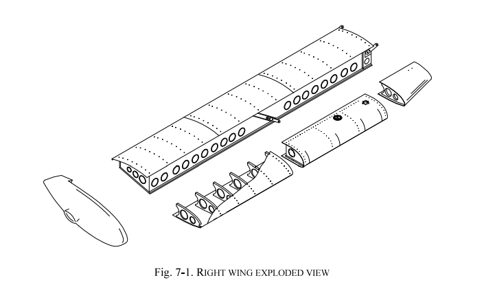
The wing is built with a central box made of light alloy; an aluminum leading edge with integrated fuel tank is attached to the front spar while flap and aileron are hinged to the rear spar. The flaps are built with a central spar to which the front and rear ribs are joined; wrap-around aluminum panels cover the flap structure. The aileron is built with an aluminum spar to which a formed leading edge and sheet metal ribs are attached; a wrap-around thermosetting synthetic material covers the aileron structure.
The forward part of the fuselage is made of a mixed structure: a truss structure with special steel elements for the cabin survival cell, and a light alloy semi-monocoque structure for the lower cabin section. The rear part of the fuselage is built with an aluminum alloy semi-monocoque structure. The engine compartment is insulated from the cabin by a stainless steel firewall; the steel engine mount longerons are connected to the cabin truss structure at four points.
The vertical tail is all-metal: the vertical stabilizer consists of a double spar with stressed skin while the rudder is composed of an aluminum torque spar connected to light alloy ribs and skin. The horizontal tail is of the all-moving type (stabilator); its structure is composed of a tubular aluminum spar connected to ribs and leading edge; a wrap-around heat-shrink synthetic material covers the stabilator structure.
The aircraft flight controls are operated through conventional stick and rudder pedals. The longitudinal control acts through a system of push-rods and is equipped with a trim tab. The aileron control is of mixed type with push-rods and cables; the cable control circuit is confined within the cabin and is connected to a pair of push-rods positioned in the wings that control the ailerons differentially. Aileron trimming is performed on ground through a small tab positioned on the left aileron.
The flaps are extended by an electric servo actuator controlled by a switch on the instrument panel. The flaps act continuously, the indicator shows the two positions relative to takeoff (15°) and landing (38°). An automatic circuit breaker positioned on the right side of the instrument panel protects the electrical circuit.
The longitudinal trimming is performed by a small tab positioned on the stabilator and controlled by an electric servo by pressing an Up/Down button on the control stick. A selector switch located on the instrument panel enables control from the left or right stick; additionally, a safety switch positioned by the trim indicator interrupts power from the circuit in case of emergency (see section 3).
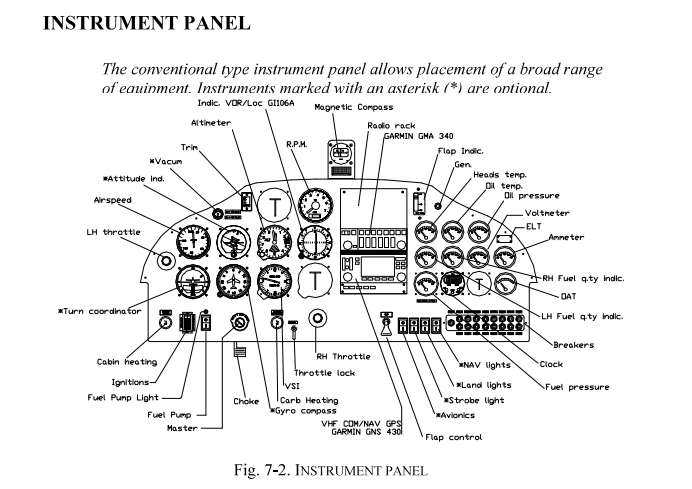
The conventional type instrument panel allows the positioning of a wide range of equipment. Instruments marked with an asterisk (*) are optional.
The carburetor heat knob is square shaped and is located just to the left of the central throttle control; when the knob is pulled fully out from the instrument panel, the carburetors receive maximum hot air. During normal operation, the knob is OFF.
The cabin heat knob is positioned in the lower left part of the instrument panel; when the knob is pulled fully out, the cabin receives maximum hot air. The vents are positioned near the rudder pedals and above the instrument panel. If necessary, fresh outside air can be circulated inside the cabin by opening the door vents.
It is possible to adjust the throttle friction lock by appropriately tightening the friction lock disc positioned on the instrument panel near the central throttle control.
The aircraft is equipped with three-point safety belts with adjustable lap and diagonal straps through a sliding metal buckle. The seats are built with a light alloy tubular structure and synthetic material padding. A lever positioned on the lower right side of each seat allows seat adjustment according to pilot size.
The aircraft doors are equipped with external and internal handles with lock provided externally on the left side. An internal safety locking mechanism is positioned near the upper edge of the door and must be used before flight to secure the door. The mechanism rotates to hook the door frame to the cabin tubular structure.
The baggage compartment is located behind the pilot seats. Baggage must be evenly distributed on the service shelf and its weight must not exceed 20 kg. Secure the baggage using the adjustable tie-down net.
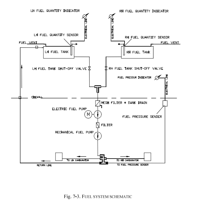
The system is equipped with two aluminum fuel tanks integrated in the wing leading edge and accessible for inspection through dedicated covers. The capacity of each tank is 35 lt (45 lt optional) and the total usable fuel is 66.8 lt (86.8 lt). Each tank is equipped with a shut-off valve installed in the cabin. A strainer with drain valve (Gascolator) is positioned on the engine side of the firewall. Fuel level indicators for each tank are positioned on the instrument panel.
Fuel delivery occurs through a mechanical pump driven by the engine and through an electric pump for emergencies (normally ON for takeoff) that provides adequate fuel supply to the engine in case of main pump failure. All fuel lines located in the engine compartment are protected with fire-resistant sheathing to prevent possible fires. Figure 7-3 illustrates the fuel system schematic.
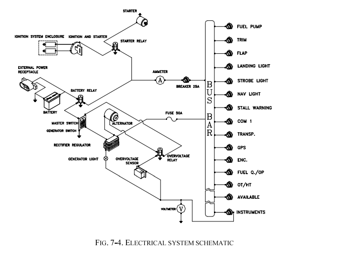
The aircraft electrical system consists of a 12 Volt DC circuit controlled by the Generator switch positioned on the instrument panel. Electricity is supplied by an alternator and a buffer battery positioned in the tail section of the fuselage. The generator warning light is positioned on the right side of the instrument panel.
The generator warning light (red) illuminates under the following conditions:
The battery can support energy requirements for 26 minutes (see page 3-8).
The voltmeter indicates the bus bar voltage; a positive ammeter value indicates the generator is charging the battery, a negative value indicates the battery discharge rate.
These instruments are connected in series with their respective sensors. The same circuit breaker protects all temperature instruments while a second breaker protects the oil pressure indicator and other instruments.
A digital outside air temperature indicator (°C) is positioned in the upper left part of the instrument panel. The sensor is positioned on the upper part of the cabin.
The aircraft is equipped with a stall warning system consisting of a sensor positioned on the leading edge of the right wing connected to an audible warning horn positioned on the instrument panel.
The central part of the instrument panel houses the avionics equipment. The manufacturer of each individual system provides the characteristics for each system.
On the right side of the tail cone there is an external power receptacle. Using this device it is possible to power the electrical system from an external power source. It should be used for engine starting in cold conditions.
Follow this procedure to start the engine using external power:
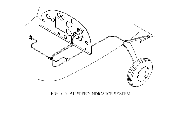
The aircraft airspeed indicator system is shown below and consists of two static ports positioned on the sides of the aircraft forward of the cabin and a Pitot tube positioned on the left wing strut.
The aircraft braking system is a single system that acts on both main gear wheels through disc brakes, the same circuit serves as parking brake through a shut-off valve.
To activate the brakes, simply verify that the brake shut-off valve positioned on the tunnel between the pilots is OFF, then activate the brake lever as needed.
To activate the parking brake, pull the brake lever and set the brake shut-off valve to ON.
To compensate for magnetic compass deviation errors, the following correction card is positioned immediately below the compass:
| For | N | 30 | 60 | E | 120 | 150 |
| Steer | ||||||
| For | S | 210 | 240 | W | 300 | 330 |
| Steer | ||||||
| DATE | RADIO ON | AIRPATH | ||||
This placard must be filled out by a certified operator with valid and appropriate instrumentation.
The following placard is positioned on the cabin floor tunnel, near the brake hydraulic circuit shut-off valve:
Two throttle control knobs are positioned on the instrument panel. One is positioned centrally while the other is on the upper left side. The following placard is near each:
A throttle friction lock is positioned on the instrument panel to maintain the desired setting. The following placard is positioned near the friction lock:
The fuel shut-off valves are positioned on the forward members of the cabin truss. The RH valve shuts off flow from the RH tank; the LH valve shuts off flow from the LH tank. When the valve lever is aligned with the truss member, the valve is open; if the lever is rotated 90° from the truss member, the valve is closed.
The cabin heat knob is positioned in the central area of the instrument panel just to the right of the throttle control:
The carburetor heat knob is positioned in the central area of the instrument panel just to the left of the throttle control:
The trim switch control is positioned in the upper central area of the instrument panel alternating trim control to the RH or LH stick:
A switch positioned in the upper central area of the instrument panel interrupts power to the trim system in case of malfunction:
The circuit breakers are positioned on the lower right side of the instrument panel and each is individually marked as follows (from left to right):
The flap control switch is positioned in the lower part of the instrument panel, slightly to the right:
A 74x7 mm placard is positioned on the instrument panel to indicate the fire extinguisher location:
The Generator and Master switches are positioned in the lower left part of the instrument panel:
A generator warning light is positioned in the upper right part of the instrument panel:
The antifreeze liquid overflow tank cap bears the following placard:
The brake fluid reservoir cap bears the following placard:
The following placard is positioned near the fuel filler caps (28x63mm):
The following placards are positioned on the oil tank:
The following label is positioned under each door for emergency opening:
The main gear tire inflation pressure is indicated in the following label affixed to each leaf spring:
The following label indicates the inflation pressure for the nose gear tire (32 psi if 5.00 tire is installed and 15 psi if 4.00 tire is installed):
The 0° reference for stabilator balancing is positioned on the left side of the tail cone near the stabilator:
The following aircraft identification placard is positioned on the tail cone:
On the right side of the tail cone, next to the battery access door, the following placard (69x17mm) is present:
On the right side of the tail cone, on the power receptacle door, the following placard (135x25mm) is present:
On both main gear fairings the following placard (120x22mm) is present:
P92-JS FLIGHT MANUAL - SECTION 7: AIRCRAFT DESCRIPTION AND SYSTEMS
Edition 3 - Revision 5 - July 12, 2022
English translation for educational purposes - Always refer to the original document