×
![Enlarged image]()
SECTION 9 - SUPPLEMENTS
This section contains supplements to the Flight Manual for optional equipment and specific configurations of the P92-JS aircraft.
1 - Introduction
This section contains supplemental information for safe and efficient operation of the aircraft if equipped with the Garmin GNS 430 system.
1.2 - General
- The GNS 430 GPS Global Positioning System is an integrated system that contains a GPS navigation system plus a VHF COMM transceiver and a VOR/ILS receiver.
- The system includes a GPS antenna, GPS receiver, VOR/LOC receiver, VHF Comm antenna and VHF Comm transceiver.
- The main function of the VHF Comm is to allow communication with the control tower.
- The VOR/ILS function is dedicated to receiving and demodulating VOR and LOC signals.
- The GPS section is dedicated to acquiring signals from the GPS satellite system and providing real-time information regarding position, speed and time.
- With appropriate signals the GNS 430 GPS can:
- Plan VFR/IFR routes, trace waypoints and plan non-precision approaches (GPS, LORAN-C, VOR, VOR-DME, TACAN, NDB, NDB-DME, RNAV) in accordance with AC 20-138
- The reference coordinates used for navigation are WGS-84.
1.3 - Limitations
- The "Pilot's Guide and Reference" p/n 190-00140-00 rev. F dated July 2000 or later versions must be available for proper use of the instrument.
- Only VFR use is permitted.
- The GPS section must use the following software versions (or more recent approved versions):
| Subsystem | Software Version |
|---|
| MAIN | 2.00 |
| GPS | 2.00 |
| COMM | 1.22 |
| VOR/LOC | 1.25 |
Required Default Settings
The following default settings must be entered in SETUP 1 menu:
| DIS, SPD | nm kt (nautical miles and knots) |
| ALT, VS | ft fpm (feet and feet per minute) |
| MAP DATUM | WGS 84 |
| POSN | deg-min (degrees-decimal minutes) |
1.4 - Emergency Procedures
- If the information provided by the Garmin GNS430 is not available or is obviously incorrect, other navigation instruments must be used.
- If the "WARN" message appears in the lower left part of the display, the receiver cannot be considered useful as a navigation aid.
- If the "INTEG" message appears, the RAIM function is not available.
- In emergency conditions, pressing the COM flip-flop knob for 2 seconds will automatically tune frequency 121.500 MHz.
1.5 - Normal Operations
Normal operations are described in the "Pilot's Guide and Reference" P/N 190-00140-00 rev. F dated July 2000 or later versions.
1.6 - Performance
No change.
1.7 - Weight and Balance
See Section 6 of this manual.
1.8 - Systems
See "GNS 430 Pilot's Guide" for a complete system description.
2 - Introduction
This section contains supplemental information for safe and efficient operation of the aircraft if equipped with a banner towing hook (Mod. Number 92/27).
2.3 - Limitations
Maximum banner dimensions: 140 m²
MTOW with 140m² banner: 460 kg
Maximum airport altitude: 3000 ft
Minimum towing speed: 53 KIAS
Demonstrated crosswind: 5 kts
Limitation Placards
MINIMUM TOWING SPEED = 53 KIAS
CONSULT SUPPLEMENT 9.2
OF THE FLIGHT MANUAL
FOR LIMITATIONS DURING
TOWING OPERATIONS
2.4 - Emergency Procedures
Emergency Banner Release
- Identify a safe location on the ground for banner release
- Activate the release lever
If the banner is released correctly:
- Control the aircraft
- Land
If the banner does NOT release:
- Flaps: as required
- Engine throttle: as required
- Set glide to have the banner touch down at runway threshold
- Check banner position
- Land
2.5 - Normal Procedures
Cabin Inspection
- Weight and airport altitude: verify compatibility
- Release lever: check
External Inspection
- Rear-view mirror: adjust and verify attachment
- Release hook: verify functionality
Before Takeoff
- The banner will be deployed along the runway or properly positioned folded
- Position the banner behind the aircraft to straighten the towing lines
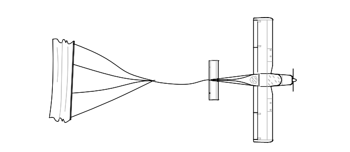
Fig. 9-1: Banner positioning before takeoff
CAUTION
To reduce banner ground resistance, takeoff should be performed on a paved runway or on a short/dry grass runway.
2.6 - Performance Approved Data
Conditions (140 m² Banner):
- Flaps: 15°
- Takeoff weight: 460 kg
- Engine throttle: Full
- Runway: dry compact grass
Banner surface = 140 m²
WARNING
To achieve a takeoff climb rate of 2m/s or greater, from any altitude and temperature condition, the maximum takeoff weight (with 140m² banner) must not exceed 460 kg.
Banner Towing Equipment List
| Ref. | Description & P/N | Weight kg | Datum m |
|---|
| F1 | Towing Hook assy | 3.8 | 4.01 |
| F2 | Rear-view mirror 92-12-900-000 | 0.2 | 1.60 |
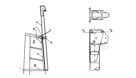
Fig. 9-2: Support beam assembly / Hook connection
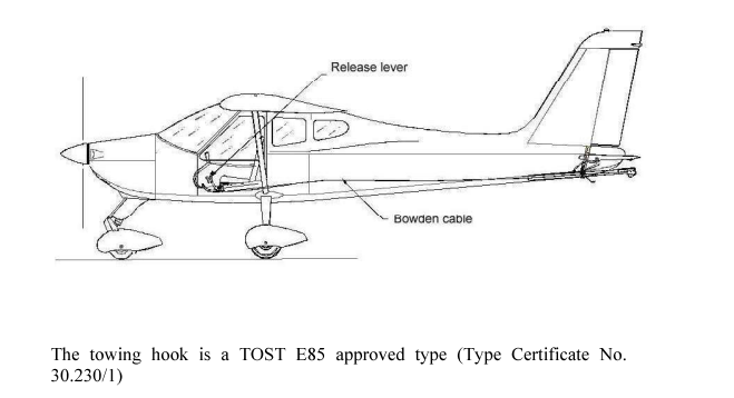
Fig. 9-3: Release lever / Bowden cable
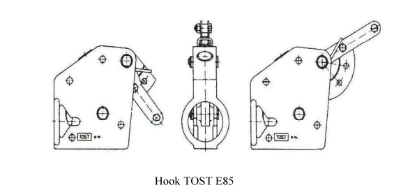
Fig. 9-4: TOST E85 Hook
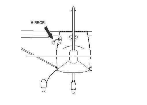
Fig. 9-5: Rear-view mirror
3 - Introduction
This section contains supplemental information for safe and efficient operation of the aircraft if equipped with the differential brake system.
3.1 - 3.6
No change from base manual.
3.7 - Systems
The left and right wheel brakes are independent systems. The system has a reservoir visible through a window in the baggage compartment. The reservoir is directly connected to the master brake cylinders.
The parking brake valve is mounted on the fuselage floor, under the seats and is activated by the lever. Each main wheel has a brake disc.
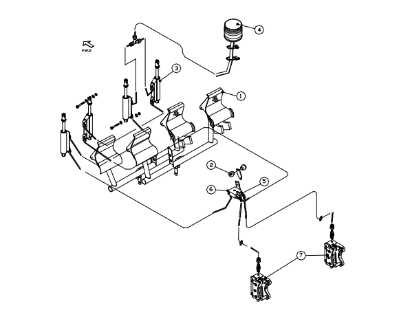
Fig. 9-6: Differential brake system
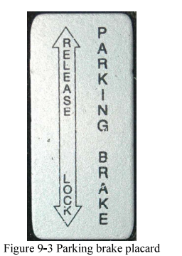
Fig. 9-7: Parking brake placard (RELEASE/LOCK - PARKING BRAKE)
4 - Introduction
This section contains supplemental information for safe and efficient operation of the aircraft if equipped with the central throttle control system.
4.1 - 4.6
No change from base manual.
4.7 - Systems
The engine throttle lever is on the left side and the choke lever is on the right side. The lever friction is on the right side of the central throttle control system.
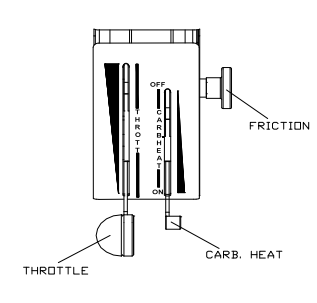
Fig. 9-3A: Central throttle system with Carb. Heat lever
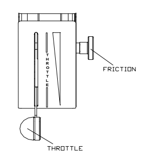
Fig. 9-3B: Central throttle system
5 - Introduction
This section contains supplemental information for safe and efficient operation of the aircraft if equipped with the new analog instrument panel.
5.2 - 5.7
No change from base manual.
5.8 - Systems
The new analog instrument panel is designed with a modular concept to improve instrument visibility.
The panel is divided into three main parts: left (flight instruments), center (avionics instruments), right (engine instruments).
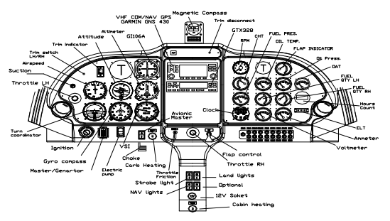
Fig. 9-4: New analog instrument panel
Revision Record
| Rev | Page | Description | Approval |
|---|
| 0 | | | DOA |
6 - Chinese Placards
| Placard | Chinese |
|---|
| THROTTLE | 油门 |
| THROTTLE LOCK | 油门阀 |
| CABIN HEAT Pull-on | 客舱加热 拉-开 |
| CARB. HEAT Pull-on | 汽化器加热 拉-开 |
| MASTER / GENERATOR ON/OFF | 主开关 / 发电机 开/关 |
| Fuel Pump ON/OFF | 油泵 开/关 |
| No smoking | 禁止吸烟 |
| NO STEP | 请勿踩踏 |
NOTE
Va=97 KIAS when the weight increase to 600 Kg is applied.
Revision Record
| Rev | Page | Description | Approval |
|---|
| 0 | | | DOA |
7 - Introduction
This section contains supplemental information for safe and efficient operation of the aircraft delivered in Argentina.
7.3 - Limitations
WARNING
The limitations, operations and performance associated with 600 Kg MTOW are applicable only for aircraft that incorporate modification MOD 92/41, or apply Service Bulletin SB 011-CS as retrofit.
7.3.1 - Fuel
| APPROVED FUEL | MOGAS ASTM D4814
AVGAS 100L (ASTM D910) |
7.3.2 - Required Equipment
The aircraft, in standard configuration, is approved only for day VFR operations with visual terrain contact.
7.3.3 - Limitation Placards
The following placard will be on the left side of the dashboard:
NO FUMAR
Near the baggage compartment the following placard will be present:
ASEGURAR LA RED
PESO MÁXIMO 20 Kg
MÁXIMA PRESIÓN 12,5 Kg/dm²
7.8 - Aircraft Description and Systems
Additional placards:
EXTINTOR DE INCENDIO EN
EL PISO DEL COMPARTIMIENTO DE EQUIPAJE
MOGAS ASTM D4814
AVGAS 100LL (ASTM D910)
CAPACIDAD 45 Lt (11,9 US gal)
EN CASO DE EMERGENCIA
TOME LA MANIJA Y
TIRE CON FUERZA DE AQUÍ.
CONEXIÓN DE ENERGÍA EXTERNA
12 VOLT - DC
BATERÍA ADENTRO
NO PISAR
P92-JS FLIGHT MANUAL - SECTION 9: SUPPLEMENTS
Edition 3 - Revision 5 - July 12, 2022
English translation for educational purposes - Always refer to the original document