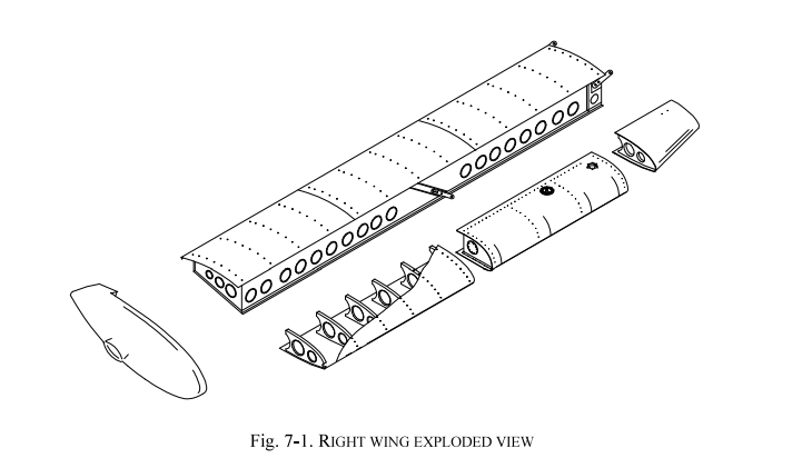
✈ TECNAM P92-JS

Aircraft Parts Quick Reference – Aero Club Roma (ATO 058)
General Data
TypeSingle-engine, two-seat, high-wing monoplane
ManufacturerTECNAM (Costruzioni Aeronautiche Tecnam S.r.l.)
MTOW600 kg
Empty weight372 kg
Landing gearFixed tricycle
ACR registrationsI-COSG, I-CALD, I-TARF, I-LARU, I-RMAR
Airframe
Wing exploded view
Wing
StructureCentral box spar in light alloy
Leading edgeAluminium with integrated fuel tank
FlapCentral spar + ribs + wrap-around aluminium panels
AileronAluminium spar + sheet-metal ribs + thermosetting synthetic skin
Fuselage
Forward sectionMixed structure: steel truss (survival cell) + light-alloy semi-monocoque
Aft sectionAluminium alloy semi-monocoque
FirewallStainless steel (isolates engine from cabin)
Engine mountSteel longerons connected to the truss at 4 points
Empennage
Vertical tailAll-metal: dual-spar stabiliser + stressed skin; rudder with aluminium torque spar
Horizontal tailFully-moving stabilator: tubular aluminium spar + ribs + heat-shrink synthetic skin
Flight Controls
Control typeConventional stick and rudder pedals
Pitch controlPush-rod system + trim tab
Aileron controlMixed push-rod and cable, differential actuation
Aileron trimGround-adjustable tab on left aileron
FlapElectric servo-actuator, continuous action
Takeoff flap setting15°
Landing flap setting38°
Pitch trimElectric servo, Up/Down button on control stick
Trim selectorLH/RH switch on instrument panel
Trim disconnectSafety switch on panel (emergency)
Powerplant
EngineROTAX 912S2
Type4-stroke, 4-cylinder horizontally opposed
CoolingCombined air and liquid
IgnitionDual electronic ignition
LubricationForced
Max power98.6 hp (73.5 kW) @ 5800 rpm
Max propeller RPM2388 rpm
Reduction ratio2.4286:1
PropellerTwo-blade wooden HOFFMANN HO17GHM-174 177C
RPM Tachometer Oil Pressure Oil Temp EGT CHT
Coolant: 80% antifreeze + 20% water
Fuel System
Tanks2 aluminium tanks in wing leading edge
Capacity per tank35 lt (45 lt optional)
Total usable fuel66.8 lt (86.8 lt with option)
Fuel typeAVGAS 100LL (density 0.75 kg/lt)
Shut-off valves2 valves in cabin (LH/RH), lever aligned=open, rotated 90°=closed
Mechanical pumpEngine-driven
Electric pumpEmergency (ON for takeoff)
Sediment filterGascolator with drain valve (engine side of firewall)
Fuel system schematic
Fuel gauge Fuel pressure
WARNING: Fuel level gauges are for reference only! The PIC must verify the actual quantity before departure.
Electrical System
Voltage12 Volt DC
GeneratorAlternator, controlled by panel switch
BatteryBuffer battery, located in tail section
Battery endurance26 minutes (without generator)
ALT light (red)Generator or regulator/rectifier failure
Voltmeter-AmmeterPositive=battery charging, Negative=discharging
External powerSocket on tail cone (cold start)
Electrical schematic
Voltmeter Strobe Landing light
Circuit Breakers (left to right)
BATT 25AMain battery
STALL 1AStall warning
OT/HT 3AOil temp / Cylinder head temp
Televel/OP 3AFuel level / Oil pressure
INSTR 7.5AInstruments
TRIM 3ATrim
FLAP 7.5AElectric flaps
STROBE 5AStrobe lights
Land.L 10ALanding light
Fuel PUMP 7.5AElectric fuel pump
COM. 10ACommunication radio
GPS 5AGPS
Transp. 3ATransponder
ENC. 2AAltitude encoder
Audio 5AAudio panel
NAV L. 7.5ANavigation lights
Pitot-Static System
Pitot-static system
Pitot tubeOn left wing strut
Static ports2 ports on fuselage sides, forward of cabin
Connected instrumentsAirspeed Indicator (ASI), Altimeter (ALT), Vertical Speed Indicator (VSI)
Brakes
TypeDisc brakes on main landing gear wheels
ActuationSingle brake lever (acts on both wheels)
Parking brakePull brake lever + shut-off valve to ON
Brake fluidMIL H5606
Instrument Panel – Key Controls
Instrument panel ✈ Open Interactive Cockpit
Airspeed Indicator Altimeter VSI Turn Coordinator Directional Gyro Tachometer
Carburettor heatSquare knob, left of throttle. Pulled=hot air, pushed=OFF
Cabin heatKnob on lower left panel. Pulled=hot
Throttle friction lockLocking disc near centre throttle
Stall warningSensor on right wing leading edge + audible warning on panel
OATDigital indicator (degrees C), upper left panel. Sensor above cabin
GPS/NAV/COM Transponder Audio panel Trim/Flap OAT Hobbs
Master switchLower left panel
Generator switchNext to Master
Ignition keyOFF / R / L / BOTH / START
WARNING: If key is on L, R or BOTH, an accidental movement of the propeller can start the engine!
Reference Speeds
SpeedValue
Vr (Rotation)55 KIAS
Vy (Best Rate of Climb)73 KIAS
Vx (Best Angle of Climb) @ 550kg63 KIAS
VA (Manoeuvring)97 KIAS
VNO (Max Structural Cruising)110 KIAS
VNE (Never Exceed)141 KIAS
VFE (Flaps Extended)71 KIAS
Best Glide69 KIAS
Max Crosswind15 KTS
Engine failure after takeoff60 KIAS
Engine failure in flight69 KIAS
Cabin – Seats, Doors, Baggage
SeatsLight-alloy tubular frame + synthetic padding. Adjustable via lever on lower right side
Harnesses3-point: lap belts + diagonal strap, sliding metal buckle
DoorsInternal/external handles. External lock on left side. Internal safety lock (upper edge, rotate to latch)
Baggage compartmentBehind seats, max 20 kg, use restraint net
Fire extinguisherOn baggage compartment floor
Important Placards
PARKING BRAKEFloor tunnel, near brake valve
THROTTLENear each throttle (centre + LH)
THROTTLE LOCKNear friction lock (+/−)
LH/RH FUEL SHUT-OFFOn cabin truss members
CABIN HEAT Pull-onCentre panel, right of throttle
CARB. HEAT Pull-onCentre panel, left of throttle
TRIM SWITCH LH/RHUpper centre panel
TRIM DISCONNECTUpper centre panel (emergency)
FIRE EXTINGUISHEROn baggage compartment floor
← Back to Homepage
Source: AFM P92-JS Ed2 Rev1 – Sec. 7
Aero Club di Roma – PPL NIBBIO IV
×